Enture Views - Diagram View
Diagram View
To create a Diagram View, you must create a name for the view, choose the view type as Diagram View, enter a description, and click the submit button. Then, your Diagram View will be created, and the name (for example, “Diagram View”) you have given will be displayed on the tab.
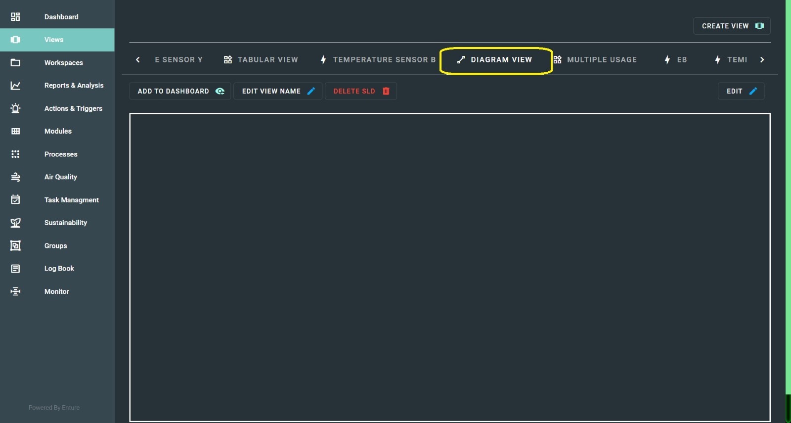
The Diagram View allows you to draw your SLD (Single Line Diagram), a pictorial representation of your machines and equipment, providing a clear diagrammatic view.
To draw the SLD, click on the Edit option in the right corner. You will see a diagram area with:
- Zoom in and Zoom out options
- A plus icon providing three options
- Ability to drag the viewport and zoom in/out images

a. Components
This option provides two additional features:
- Add Text – Allows you to insert text anywhere in the diagram.
- Add Realtime Data – Streams real-time data of the SLD you create.
b. Shapes Palette
This option displays a list of shapes needed to create an SLD.
You can select shapes from the palette, and the chosen shape will appear in the right panel. To add it to the diagram area, click “Add Selected”.

c. Line Palette
This option allows you to choose a line from the dropdown (as shown in the image below). These lines are essential for mapping your images to create an SLD.

Note:
All shapes and lines you add can be edited or removed by right-clicking on the image if not required.
These three options enable you to create a well-structured diagrammatic representation in Diagram View.
Once your diagram is complete, click the Save button in the top-right corner to save your view.